OSPF Network Advertisement
MPLS Lab: Log Entry #1
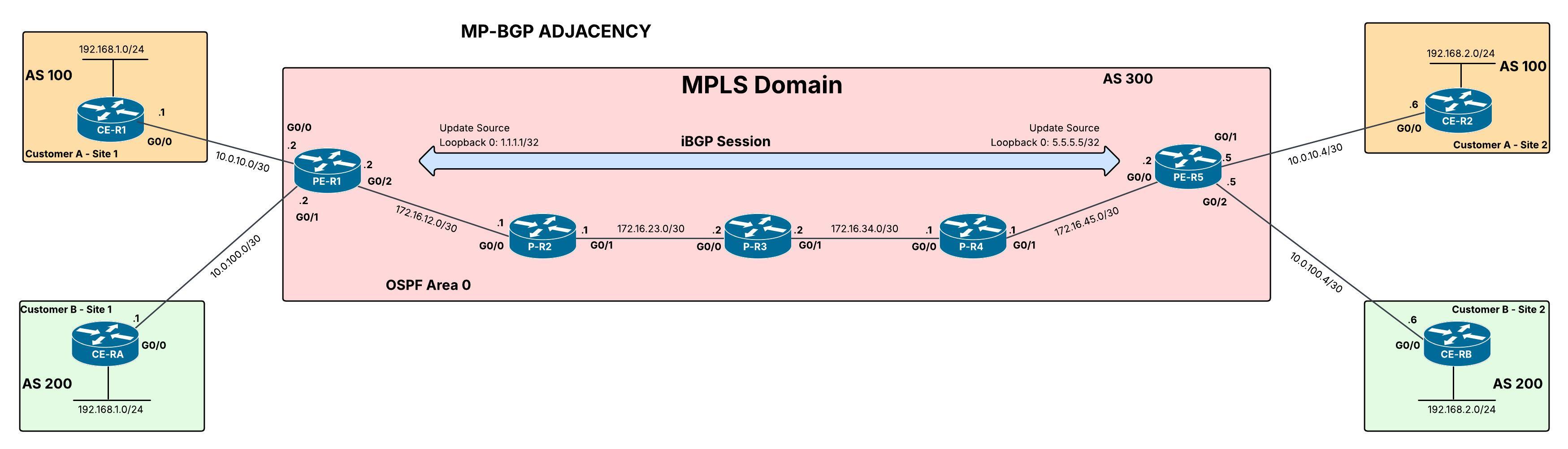
The first step I will take to begin configuring the lab is establishing end-to-end reachability between the Provider routers within the MPLS domain using OSPF as the IGP. This is critical to the MPLS infrastructure because it provides the underlay needed for LDP label exchange across the MPLS core.
In this post we will:
- Advertise networks into OSPF
- Perform minor OSPF tuning
- Verify config using show commands and packet inspection
Enabling OSPF and Advertising Networks
There are two ways to advertise networks into OSPF.
- Network statements
- Directly assigning an interface to an OSPF area
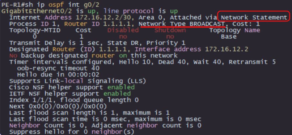
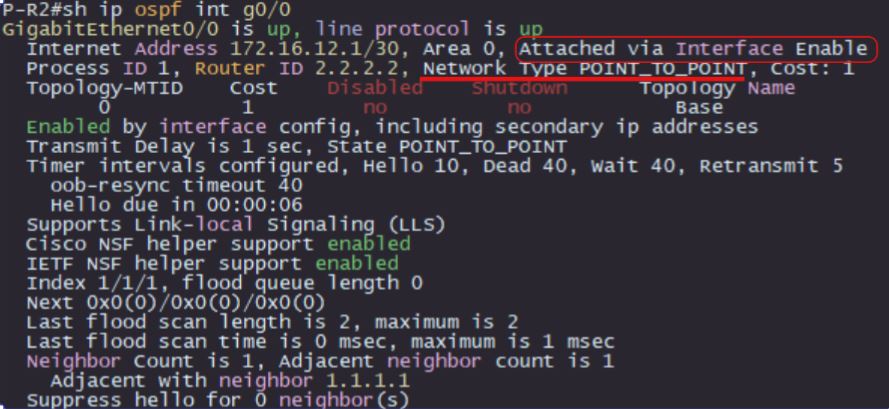
I prefer network statements because it organizes the OSPF configuration in a centralized area versus the config being scattered across interfaces. I will show both methods via verification commands.
To start, we want PE-R1 and P-R2 to form a neighbor adjacency and participate in OSPF. We configure their interfaces so that they are advertised into OSPF area 0, which we can see from the output below.
1
2
3
4
5
PE-R1(config-if)#do sh run | sec ospf
router ospf 1
 router-id 1.1.1.1
 passive-interface default
 network 172.16.12.0 0.0.0.3 area 0
1
2
3
4
5
P-R2(config-if)#do sh run | sec ospf
 ip ospf 1 area 0
router ospf 1
 router-id 2.2.2.2
 passive-interface default
As you can see, there is a slight difference between how the OSPF config presents itself between the two devices. On PE-R1, you can clearly see which networks are being advertised via the network statements whereas, on P-R2, the interface where the OSPF config is applied is not shown. Still, there is another verification command you can use to show all interfaces participating in OSPF. That command is, show ip ospf interface brief, with the output presented below:
1
2
3
PE-R1(config-if)#do sh ip ospf int b
Interface    PID   Area            IP Address/Mask    Cost  State Nbrs F/C
Gi0/2        1     0               172.16.12.2/30     1     DR    0/0
1
2
3
P-R2(config-if)#do show ip ospf interface br
Interface    PID   Area            IP Address/Mask    Cost  State Nbrs F/C
Gi0/0        1     0               172.16.12.1/30     1     DR    0/0
There is one problem though, the neighbor adjacency still has not formed. We can confirm that from the output of 0/0 under Nbrs F/C and the fact that there are 2 designated routers on a signal link. Review the show run | sec ospf output above for a clue as to why.
The reason the adjacency did not form, is because of the passive-interface default command. This command is used to prevent interfaces from sending hello messages and stops them from processing incoming hello messages, preventing OSPF adjacencies from forming. It is best practice to implement this command to halt the formation of adjacencies on untrusted VLANs that are exposed to end devices and to decrease bandwidth utilization by suppressing the unnecessary flooding of OSPF packets.
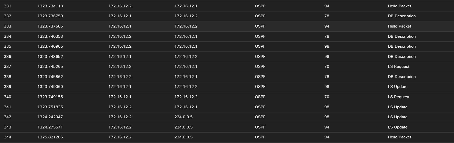
To initialize forwarding of OSPF packets, we must use the no passive-interface interface-id command as shown below. You can see that the OSPF adjacency formed right away along with the OSPF packets that were exchanged to reach a “FULL” state.
Verification
1
2
3
4
5
6
7
8
9
PE-R1(config-router)#no passive-interface g0/2
*Nov 20 22:08:12.239: %OSPF-5-ADJCHG: Process 1, Nbr 2.2.2.2 on GigabitEthernet0/2 from LOADING to FULL, Loading Done

PE-R1(config-router)#do sh ip ospf int b
Interface    PID   Area            IP Address/Mask    Cost  State Nbrs F/C
Gi0/2        1     0               172.16.12.2/30     1     DR    1/1

Neighbor ID     Pri   State           Dead Time   Address         Interface
2.2.2.2           1   FULL/BDR        00:00:38    172.16.12.1     GigabitEthernet0/2
1
2
3
4
5
6
7
8
9
10
P-R2(config-router)#no passive-interface g0/0
*Nov 20 22:08:09.623: %OSPF-5-ADJCHG: Process 1, Nbr 1.1.1.1 on GigabitEthernet0/0 from LOADING to FULL, Loading Done

P-R2(config-router)#do sh ip ospf int b
Interface    PID   Area            IP Address/Mask    Cost  State Nbrs F/C
Gi0/0        1     0               172.16.12.1/30     1     BDR   1/1

P-R2(config-router)#do sh ip ospf nei
Neighbor ID     Pri   State           Dead Time   Address         Interface
1.1.1.1           1   FULL/DR         00:00:37    172.16.12.2     GigabitEthernet0/0
Architectural Efficiency
Because this is a point-to-point(P2P) link between two routers, we are going to configure the OSPF network type as a P2P network. From a design perspective, this makes the network more efficient by removing the DR/BDR election process, resulting in faster formation of the initial neighbor adjacency. The hello packets of the P2P network type also have a different structure compared to the default broadcast network type. With the removal of the DR/BDR election, information pertaining to those entities is no longer relevant and is omitted from the hello packet. This results in an overall decrease in overhead within the OSPF control plane, improving convergence and stability. In a small network like this lab, that minor improvement is almost negligible. But in large scale environments, this optimization has compounding effects.

TLDR:
- Use an IGP protocol as an underlay for the MPLS core to provide transit needed for LDP label exchange
- You can configure OSPF via network statements or directly on interfaces.
- The use of passive-interface commands is recommended for more control over which interfaces participate in OSPF, prevents devices on untrusted networks from forming adjacencies, and decreases unnecessary flooding of OSPF packets.
- Use architectural concepts to design with intent and efficiency in mind